Getting started
This page builds a state machine diagram in OMEdit step by step: a lamp that is on for 2 s, off for 1 s, and so on.
1. Simulate an example
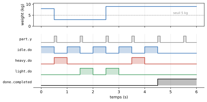
Open StateCharts.Examples.Sorting and simulate it. The diagram is a SysML state machine: a black dot (initial pseudo-state), states with compartments (idle, heavy, light), a choice diamond, a bull's eye (final state), and arrows labelled trigger [guard] / effect.
In the Plotting tab, tick idle.do, heavy.do, light.do and done.completed. The Diagram window (menu View → Windows) shows the diagram at the instant chosen with the time slider: the active state is colored green there, and the arrow of a transition turns green during its effect.
2. Create your own model
- File → New → New Modelica Class, type
model, nameLamp. - From the library browser, drag into the diagram:
- a
StateCharts.Initial(the black dot); - two
StateCharts.State, renamedoffandon; - three
StateCharts.Transition, renamedinit,switchOnandswitchOff.
- a
3. Connect states and transitions
A transition is a small block placed on the arrow: its left end (source) connects to the state it leaves, its right end (target) to the state it enters; the arrowhead shows the direction.
A state has ports on its four sides (top, right, bottom, left): an arrow may leave or enter on any side, and several arrows may leave the same state. OMEdit enlarges the port array of the side used at each connection.
- Connect the black dot to
init.source, theninit.targetto the left side ofoff. - Connect the right side of
offtoswitchOn.source, thenswitchOn.targetto the left side ofon. - To come back, flip
switchOff(right-click → Flip Horizontal), connect the bottom ofontoswitchOff.sourceandswitchOff.targetto the bottom ofoff.
4. Set the transitions
Double-click a transition:
- Trigger:
After, withdelay = 1forswitchOnanddelay = 2forswitchOff.initkeepsCompletion(no trigger). - Guard: nothing to tick here.
The label follows: after(1 s) / switchOn.
5. Use the Boolean outputs
Each state has three outputs on its right side:
entry: 0.1 s pulse at each entry into the state;do: true while the state is active;exit: 0.1 s pulse at each exit.
Each transition has an effect output (bottom right): 0.1 s pulse each time it fires. The duration of the pulses is set by pulseDuration.
Connect for instance on.do to a Modelica.Blocks.Math.BooleanToReal: its output is 1 while the lamp is on. Simulate 10 s and plot on.do, on.entry and switchOn.effect.
6. A guard on the physical model
In the Guard group, tick useGuard and write the guard, for instance sensor.T < 292.15: the transition fires only if the temperature is below 19 °C. See the Thermostat example in Examples, then The blocks for all the settings.